Iterating to Lift-Off: The Design Journey Behind Our Indoor Drone
Iterating to Lift-Off: The Design Journey Behind Our Indoor Drone
Engineering is never a straight line.
When we began the UWA ELEC5552 Indoor Surveillance Drone Project, our goal seemed simple enough: build a drone that could fly safely indoors without GPS. But between concept and first flight stood a relentless design loop of testing, failure, and iteration. Over five chassis prototypes and multiple powertrain revisions, we learned what every hardware engineer eventually realises — flight only happens when every subsystem works together.
1. Starting with Concept — Designing from Inspiration
Our earliest design sketches drew heavily from consumer drones like the DJI Tello and Mavic 2.
The focus was symmetry: even mass distribution to simplify control tuning and reduce roll bias. The first realisation, Concept 1, used an aluminium X-frame with an ABS shell, targeting rigidity above all else. It worked — until weight became the enemy. At nearly 200 g, it consumed precious thrust and power margin, leaving little room for sensors or guards.
2. Chasing Lightness — Carbon Fibre and Compromise
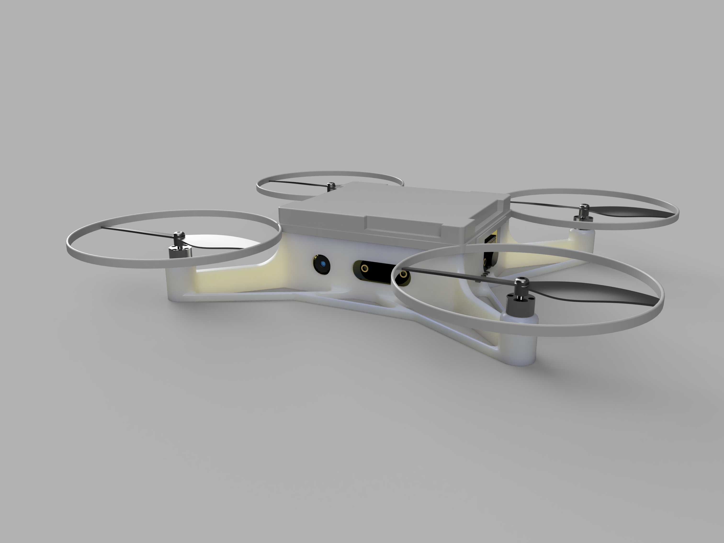
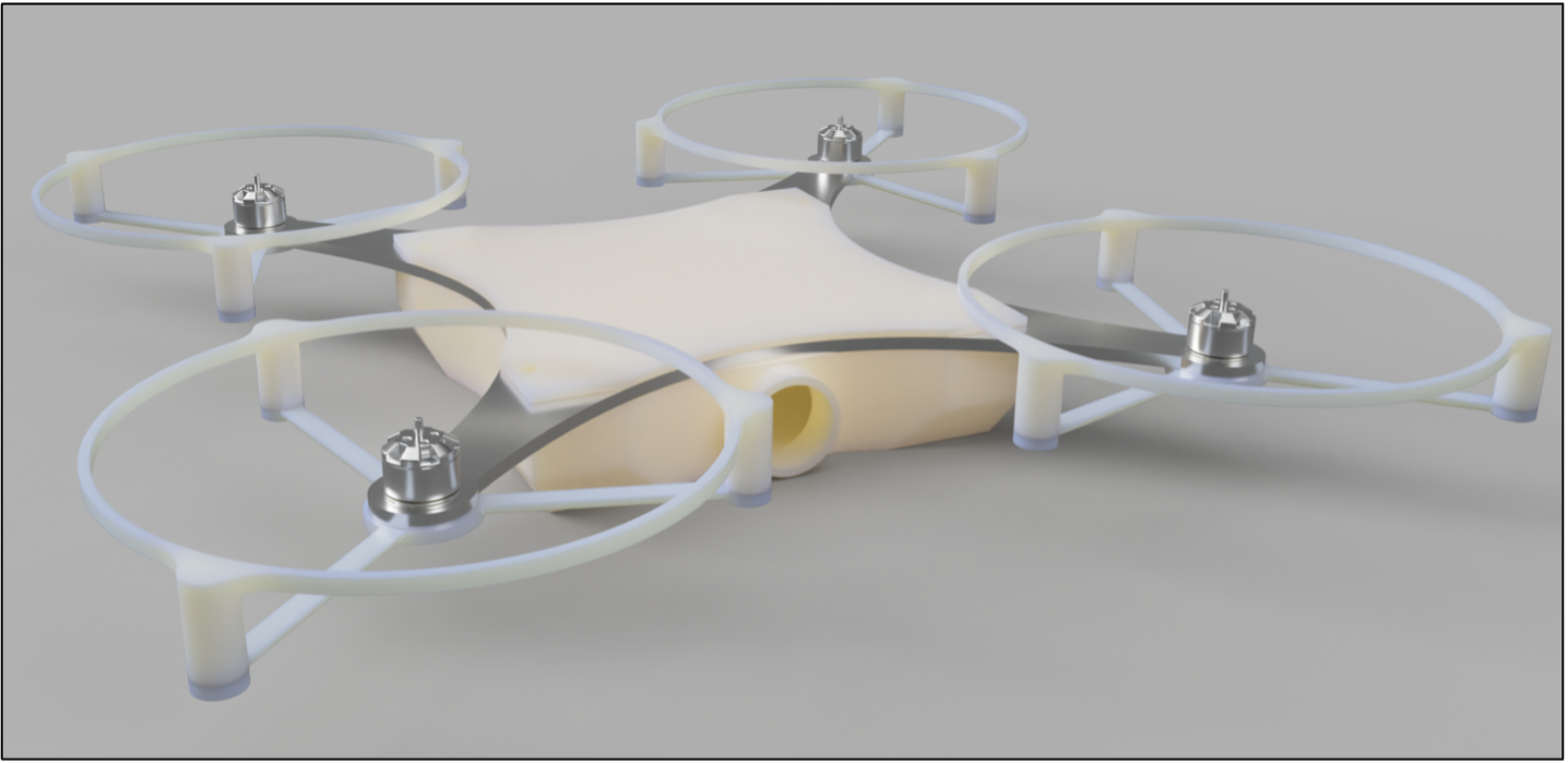
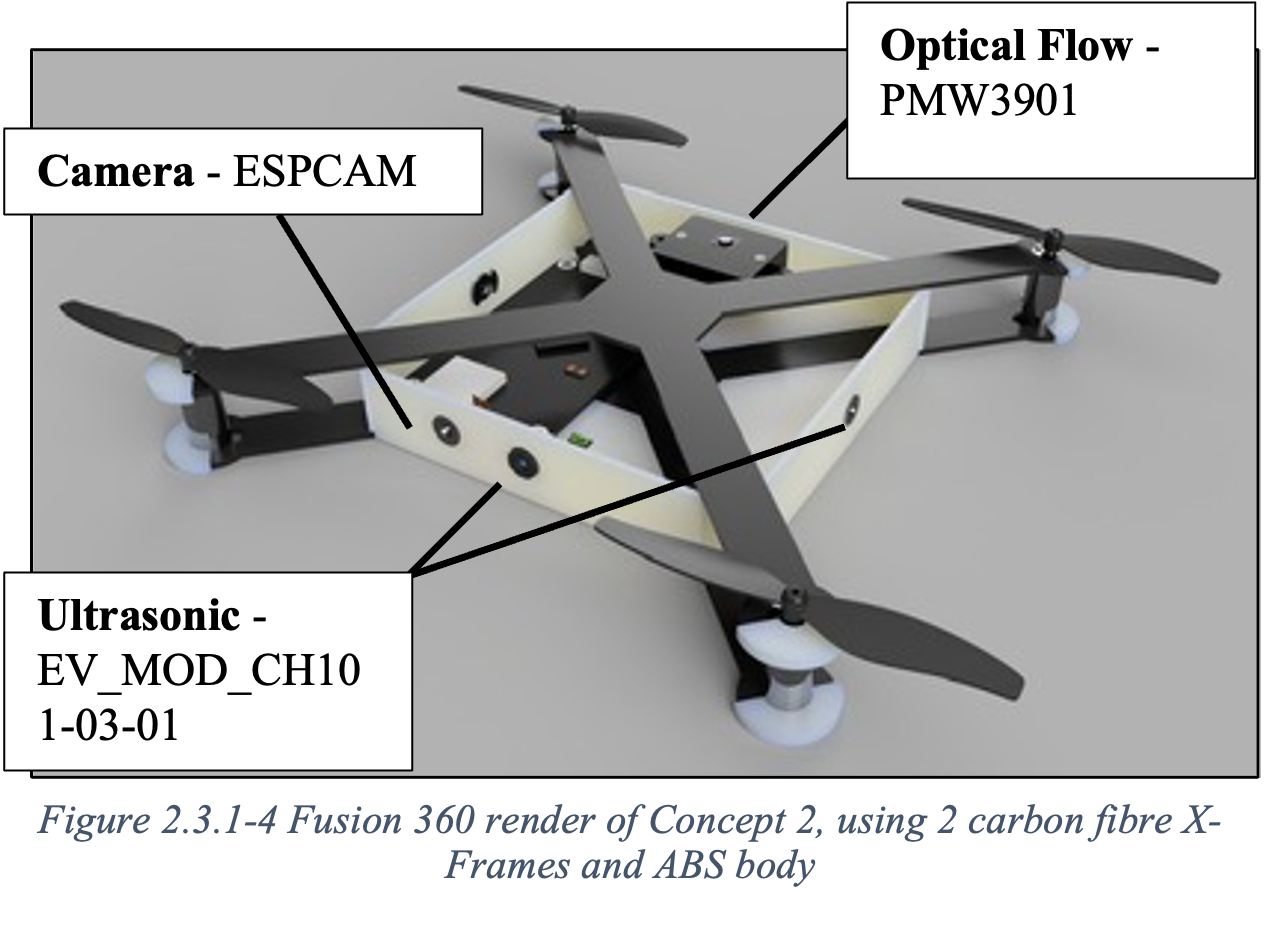
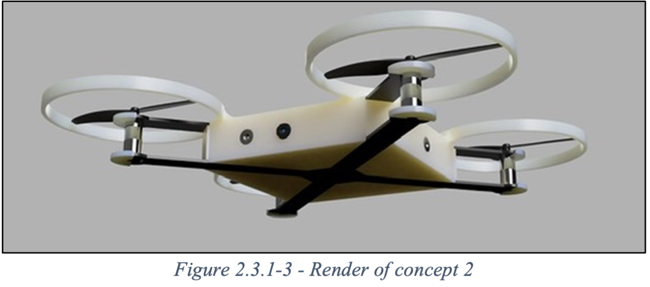
Determined to cut mass, Concept 2 shifted to carbon X-frames and ABS bodywork, trimming weight to just 60 g — one-tenth of the first prototype’s aluminium frame.
Simulations showed 70% of the torsional stiffness for 10% of the weight — promising, but manufacturing carbon fibre safely proved impractical in a student lab. Machining dust, equipment limits, and cost pushed us toward 3D-printed alternatives.
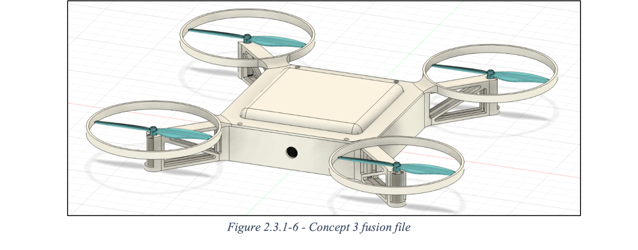
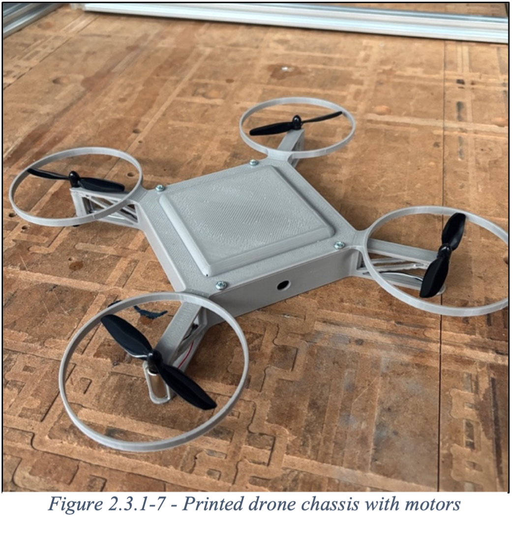
3. Discovering Structural Reality — The ABS Era
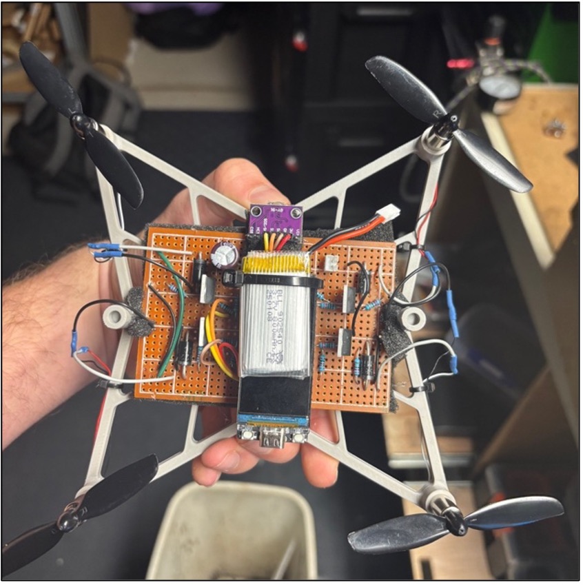
By Concept 3, we committed to 3D printing with ABS. It was accessible, recyclable, and easy to prototype. The new design featured integrated motor mounts and a protoboard-based driver system — but it came with vibration problems. The drone could lift but not hover; the frame flexed under thrust, making IMU readings unusable.
This taught us a key lesson: lightweight doesn’t mean flightworthy — structural stiffness must always exceed the control-loop frequency.
4. Learning from Failure — Balancing Weight and Rigidity
Concepts 4 and 5 became the turning points.
We adopted snap-fit joints and friction-fit motor mounts to remove screws and save grams, and thickened the motor arms to raise natural frequency above vibration zones. We found that mounting motors closer to the propeller plane drastically reduced IMU noise.
Finally, with Concept 5, the drone achieved lift-off stability — proving the “light but sufficient” design principle.
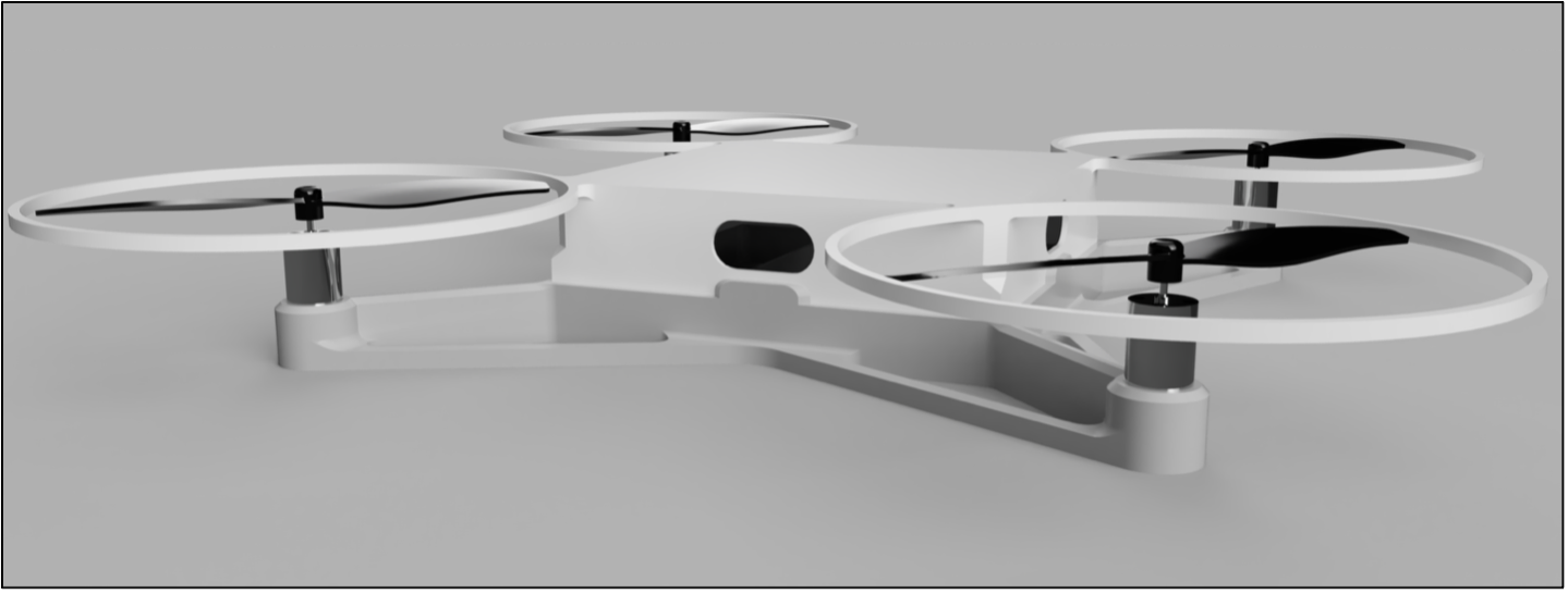
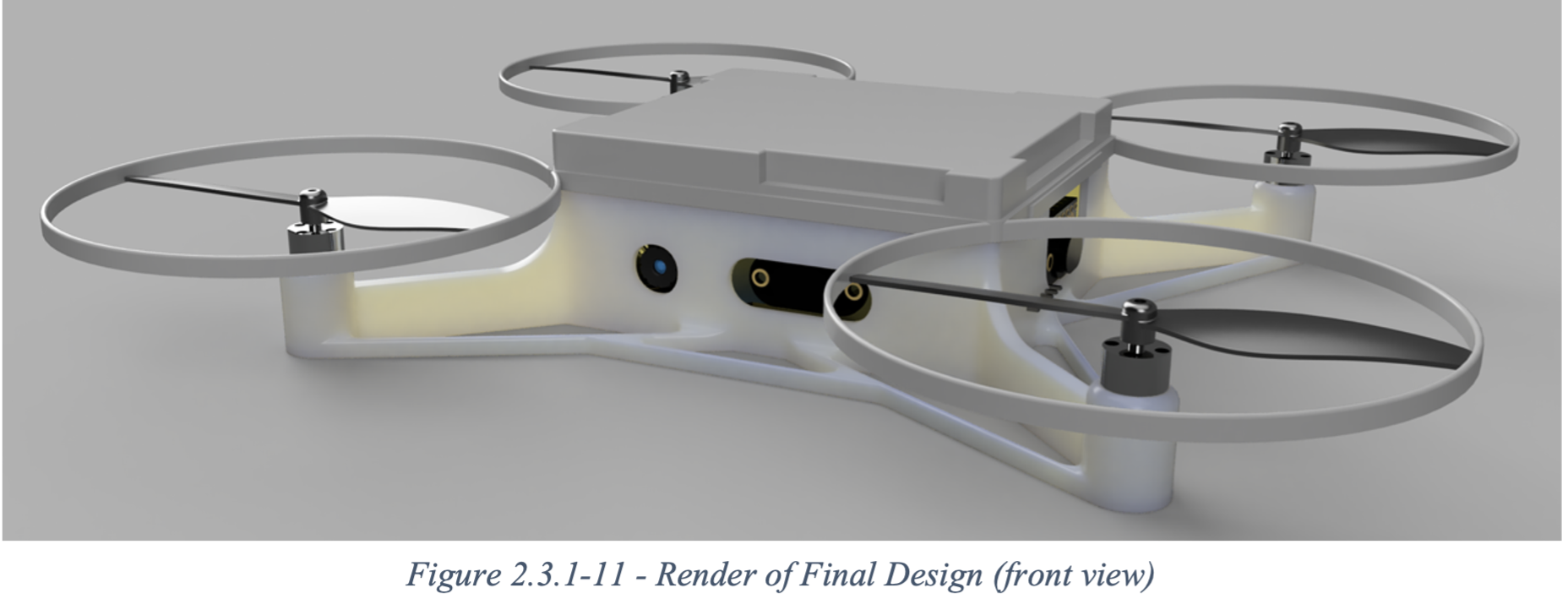
5. The Final Frame — Built for Flight, Not Show
The final 34 g chassis combined all our learnings:
ABS hybrid shell with 3 mm arms and 10 mm height for z-axis stiffness.
Tall motor towers to suppress torsional vibration.
Snap-fit assembly eliminating metal fasteners.
Modular bays for the PCB, ToF sensors, and optical flow module.
Static vibration tests confirmed that structural resonance now sat well above the 250 Hz control-loop frequency, producing stable flight and clean sensor data.
Conclusion: Designing for Failure (and Learning Anyway)
Each iteration cost us hours — but every failure taught us exactly what not to do next.
By the fifth prototype, we weren’t just building a drone; we were building a framework for disciplined engineering iteration. The final result, a stable GPS-free indoor flyer, represents far more than a successful flight — it’s a testament to process-driven design and resilience in the face of constraints.
If you’d like to follow more of our system design and embedded control projects, visit Josh-Wong.me for technical write-ups and build insights.