Building a GPS-Free Drone: Engineering Indoor Autonomy from Scratch
Building a GPS-Free Drone: Engineering Indoor Autonomy from Scratch
When you remove GPS from a drone, everything changes.
Our challenge in ELEC5552 was to design a safe, fully autonomous quadcopter that could navigate within a closed lab — no satellite data, no external positioning systems, and no tolerance for collisions. The result was a custom-built indoor drone that blends lightweight hardware, embedded control, and real-time sensor fusion into one cohesive system.
1. The Mission: GPS Denied, but Precision Required
Indoor operation means no GPS and unpredictable reflections off walls and floors.
Our goal: create a drone capable of hovering within ±0.1 m, detecting obstacles within 0.5 m, and navigating a predefined path for at least 3 minutes of flight time.
To achieve this, the design had to satisfy multiple constraints simultaneously:
Weight limit: < 250 g to meet CASA micro-RPA category.
Safety: software kill-switch and propeller guards mandatory.
Autonomy: operate purely from onboard sensors and control logic.
2. System Architecture: A Lightweight, Intelligent Core
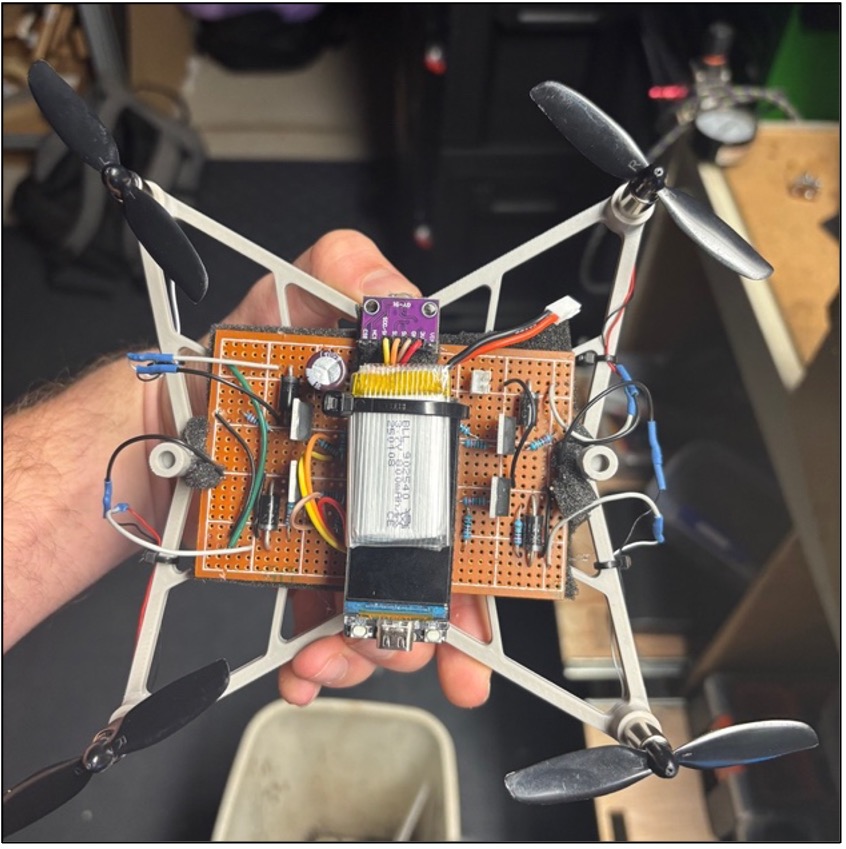
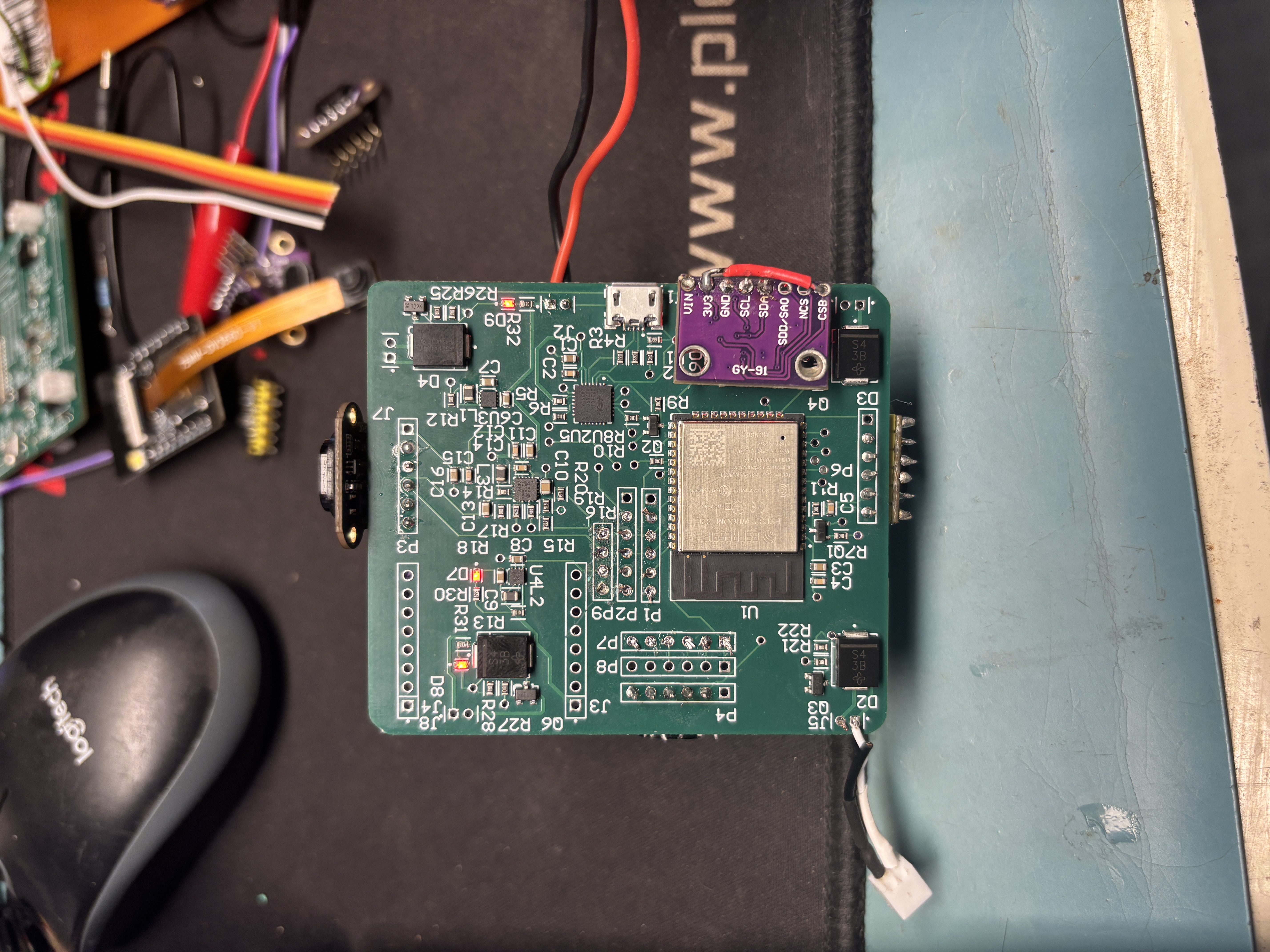
We built around an ESP32-WROOM microcontroller on a custom 4-layer PCB, merging flight control, power regulation, and sensor interfaces.
Key subsystems:
Propulsion: 4 × 8520 brushed DC motors, PWM-driven at 18 kHz for quiet, smooth thrust.
Sensing: VL53L1X ToF sensors for altitude and obstacle detection, and a PMW3901 optical-flow module for planar odometry.
Communication: a Wi-Fi-based web interface providing arming, live telemetry, and a watchdog-backed kill switch.
This architecture allowed closed-loop hover control and navigation with deterministic latency below 200 ms — essential for safety in confined spaces.
3. Chassis: From Overbuilt to “Light-but-Sufficient”
Early prototypes failed because they were either too heavy (aluminium torsion-box frame) or too flexible (thin carbon flat-plates).
Through five iterations, we landed on a 3D-printed ABS hybrid:
34 g frame weight,
tall motor mounts to reduce z-axis flex and IMU noise,
snap-fit assembly eliminating screws, and
modular bays for PCB and sensors.
Static vibration tests showed the final frame pushed structural resonance safely above the control-loop frequency — a critical fix for stable IMU readings.
4. Control & Navigation: Making Sense of Chaos
The hover controller runs at 250 Hz, reading orientation and altitude to maintain a “level-at-target-height” goal.
A state machine planner executes primitives like FORWARD d, ROTATE θ, and HOLD t, while continuously checking for:
Obstacle proximity (< 0.5 m)
Link latency (> 200 ms)
Battery or sensor faults
When blocked, the planner arrests motion, sidesteps, and resumes — a simple but robust behaviour set that made early demo flights safe and predictable.
5. Testing the Limits
Over 25 structured tests validated everything from PID tuning to power-rail temperature imaging.
Key results:
Drone achieved hover stability within ±0.15 m.
Obstacle detection reliable at 0.4–0.5 m range on all axes.
System successfully auto-disarmed on link loss (watchdog < 1 s).
Remaining challenges included fine-tuning lateral drift and improving onboard power regulation under full motor load — both slated for next prototype.
Conclusion: Lessons Beyond the Drone
Designing a drone without GPS taught our team more about systems integration than any textbook could. Every decision — from the PCB stack to PID constants — was an exercise in balancing physics, electronics, and software.
Future iterations will explore:
Brushless motors for efficiency,
USB-C charging,
and carbon-fiber chassis for lighter, stiffer builds.
This project reinforced a key engineering truth: autonomy isn’t about adding complexity — it’s about making every gram, volt, and line of code count.
If you enjoyed this breakdown or want to see similar system-level builds, visit Josh-Wong.me for more technical write-ups and project updates.